- 您现在的位置:买卖IC网 > Sheet目录224 > EWN2660-0 (Power-One)PWR SUP DIN RAIL 240W 2X 24.7V
�� �
�
�W� Series� Data� Sheet�
�?�
�125,� 250� Watt� AC-DC� and� DC-DC� DIN-Rail� Converters�
�Table� 19� :� System� OK� (M1� with� external� battery� sensor)�
�System� Status�
�System� OK�
�Battery� overchared� /� temp.� sensor�
�defect� /� control� voltage� to� high�
�Overload,� converter� cannot� follow� the�
�control� signal�
�Output� does� not� follow� control� signal,�
�since� battery� would� be� overcharged�
�System� OK�
�Input�
�O.K.�
�O.K.�
�O.K.�
�O.K.�
�O.K.�
�V� control�
�sensor� signal�
�2.7� V�
�2.7� V�
�2.7� V�
�3.0� V�
�2.5� V�
�V� Bat�
�theoretical�
�27� V�
�27� V�
�27� V�
�30� V�
�25� V�
�V� Bat�
�measured�
�27� V�
�28� V�
�24� V�
�27� V�
�25V�
�Sys-OK�
�output�
�Low� ohmic�
�High� ohmic�
�High� ohmic�
�High� ohmic�
�Low� ohmic�
�V� o� =� 50� –� 100%� V� o� nom� .� R� ext1� ≈� 4� k� ?� ?� –––––––––�
�V� o� =� 100� –� 110%� V� o� nom� .� R� ext2� ≈� 4� k� ?� ?� ––––––––––––––––�
�R: Adjustment of� V� o� or� V� o2�
�The� R� input� allows� external� adjustment� of� the� output� voltage� in�
�the� range� of� 50%� to� 110%� V� o� nom� .� Double-output� models� allow�
�only� adjustment� of� output� 2� (connected� to� the� terminals� 6,� 7,� 8�
�and� 9).� This� enables� asymmetric� output� voltage� configuration.�
�Adjustment� can� be� achieved� via� a� resistor� or� an� external�
�voltage� source� (in� the� range� of� 1.25� –� 2.75� V).�
�Note� :� If� the� R� input� is� not� connected:� V� o� or� V� o2� ≈� V� o� nom� .�
�a)� Adjustment� by� an� external� resistor:�
�Resistor� R� ext1� ,� connected� between� R� (pin� 2)� and� GND1� (pin�
�1)� of� the� D-SUB� connector� or� according� to� fig.� 20.�
�V� o�
�V� o� nom� –� V� o�
�Resistor� R� ext2� ,� connected� between� R� (pin� 2)� and� VCC� (pin� 3)�
�of� the� D-SUB� connector� or� according� to� fig.� 20.�
�V� o� –� 2.5� V�
�2.5� V?(� V� o� /� V� o� nom� –1)�
�Note:� If� the� R� function� is� not� included� in� M1� or� M2,� refer� to� figure�
�20� how� to� connect� R� ext1� or� R� ext2� .�
�b)� Adjustment� by� an� external� control� voltage� V� ext� (1.25� –� 2.75�
�V),� connected� between� R� (pin� 2)� and� GND� (pin� 1)� of� the� D-�
�SUB� connector� or� according� to� fig.� 20.�
�to-phase� connection� at� low� mains� voltages� (e.g.,� USA� 120� V/�
�208� V� /� 60� Hz� systems).�
�The� built-in� second� fuse� also� enables� safe� connection� to� the�
�mains,� where� phase� and� neutral� are� not� defined� or� cannot� be�
�identified,� as� e.g.,� in� the� case� of� plug� and� socket� connection� to�
�the� mains� via� German� Schuko-plugs;� see� also� Safety� and�
�Installation� Instructions� .�
�Option� F� limits� the� DC� input� voltage� to� ≤� 250� V.�
�Q:� Reverse� Polarity� Protection�
�EW� models� have� no� bridge� rectifier� at� the� input.� To� provide�
�reverse� polarity� protection,� an� additional� diode� can� be� fitted.�
�However� this� lowers� the� efficiency� by� approximately� 1%.�
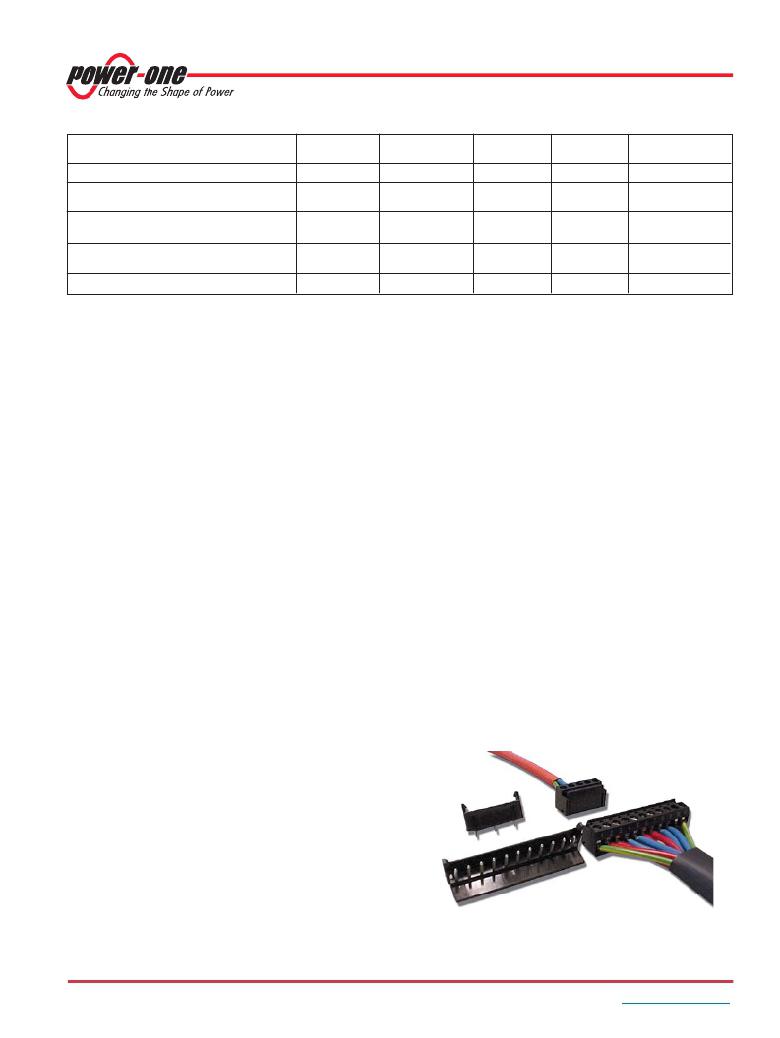
�K2:� System� Connectors�
�For� installation� in� systems� using� pre-assembled� harnesses� the�
�converters� are� available� with� system� connectors.� They� are� UL-�
�listed,� approved� for� currents� up� to� 15� A� at� –40� to� 105� °C.�
�The� mating� system� connectors� with� screw� terminals� and�
�retainers� are� delivered� together� with� every� converter� with�
�option� K2.� Use� max.� 2.5� mm� 2� (AWG� 12)� solid� or� stranded�
�wires,� or� max.� 1.5� mm� 2� (AWG� 14)� stranded� wires� with� crimp�
�termination,� stripped� length� 6� mm.� Tightening� torque� of� input/�
�output� terminals:� max.� 0.79� Nm� (7� lbs.in.).�
�G:� RoHS�
�V� ext� ≈� 2.5� V� ?� –––––�
�V� o� ≈� V� o� nom� ?� ––––�
�V� o�
�V� o� nom�
�V� ext�
�2.5� V�
�RoHS� compliant� for� all� six� substances.�
�Caution:� To� prevent� damage,� V� ext� should� not� exceed� 3� V,� nor� be�
�negative.�
�Note:� If� longer� wires� are� used� to� connect� the� R� input� at� the� D-SUB�
�connector,� the� wiring� to� pin� 1� (GND1)� should� be� done� as� star� point�
�connection.� If� wired� differently,� the� output� voltage� setting� may� be�
�adversely� affected.�
�In� battery� charging� systems,� an� external� battery� temperature�
�sensor� (see� Accessories� )� can� be� connected� to� optimize� V� o� .�
�However,� adjustment� using� the� R� input� (pin� 2� of� D-SUB)� is�
�possible� as� well.� The� above� shown� formulas� are� valid,� but�
�V� o� nom� stands� for� the� voltage� with� open� R� input� (� =� V� o� safe� ).�
�F:� Built-in� Second� Fuse�
�A� built-in� second� fuse� in� the� neutral� line� provides� safe� phase-�
�Fig.� 24�
�System� connectors� Option� K2�
�BCD20020-G� Rev� AC,� 31-Jan-2013�
�Page� 23� of� 25�
�www.power-one.com�
�发布紧急采购,3分钟左右您将得到回复。
相关PDF资料
EX-4502
BOX EXTRUD ALUM 1.57X3.14X6.96"
EX-4523
BOX EXTRUD ALUM 3.18X6.14X9.32"
EX-4543
BOX EXTRUD ALUM 9.32X3.78X3.78"
EX-AR30
SWITCH EXPLOSION PROOF SPDT 15A
EX-XR3
EXP PROOF LIMIT SWITCH SPDT
F1100BB01
FILTER GEN PURPOSE/SGL PHASE 1A
F11010102
BUTTON CAP WHITE
F1200DD30
FILTER POWER LINE EMI 30A SCREW
相关代理商/技术参数
EWN2660-0G
功能描述:DC/DC转换器
RoHS:否 制造商:Murata 产品: 输出功率: 输入电压范围:3.6 V to 5.5 V 输入电压(标称): 输出端数量:1 输出电压(通道 1):3.3 V 输出电流(通道 1):600 mA 输出电压(通道 2): 输出电流(通道 2): 安装风格:SMD/SMT 封装 / 箱体尺寸:
EWP201-011
制造商:JVC Worldwide 功能描述:ANTENNA WIRE
EWP-AA-0102-96S-ZZ-L
制造商:Finisar Corporation 功能描述:1X2 DROP, EWP SERIES, 50GHZ CHANNEL SPACING, LC CONNECTORS - Trays
EWP-AA-0104-96F-ZZ-L
制造商:Finisar Corporation 功能描述:1X4 EWP4, FLEXGRID, C-BAND, LC CONNECTORS - Bulk
EWP-EK-AA
制造商:Finisar Corporation 功能描述:EWP EVALUATION BOARD - Boxed Product (Development Kits) 制造商:Finisar Corporation 功能描述:KIT EVAL EWP PWR/SER INTERFACE
EWR1601-0
功能描述:DC/DC转换器 DIN Rail 120W (24.7V) RoHS:否 制造商:Murata 产品: 输出功率: 输入电压范围:3.6 V to 5.5 V 输入电压(标称): 输出端数量:1 输出电压(通道 1):3.3 V 输出电流(通道 1):600 mA 输出电压(通道 2): 输出电流(通道 2): 安装风格:SMD/SMT 封装 / 箱体尺寸:
EWR1601-0G
功能描述:DC/DC转换器 RoHS:否 制造商:Murata 产品: 输出功率: 输入电压范围:3.6 V to 5.5 V 输入电压(标称): 输出端数量:1 输出电压(通道 1):3.3 V 输出电流(通道 1):600 mA 输出电压(通道 2): 输出电流(通道 2): 安装风格:SMD/SMT 封装 / 箱体尺寸:
EWR-16-17
制造商:Middle Atlantic Products 功能描述: